发布人: 发布日期:2020-12-12 浏览数:3306
本文用来指导AMAT项目的管道支架的抗震做法,其中的内容是基于美国规范UBC1997关于非结构构件的抗震设计条文进行计算的。
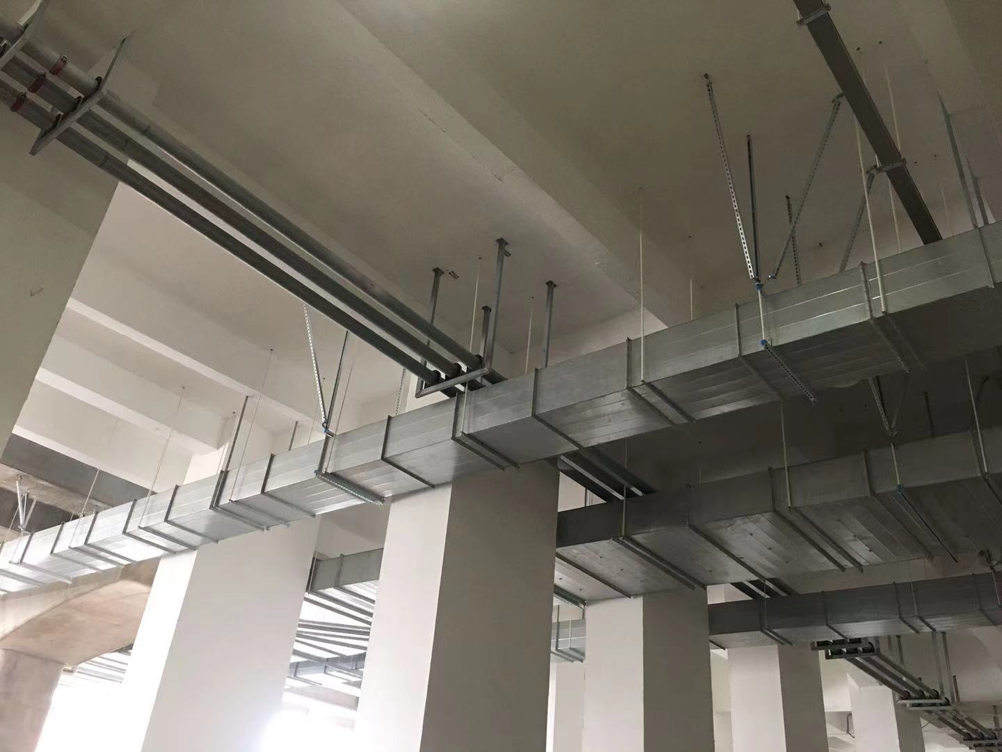
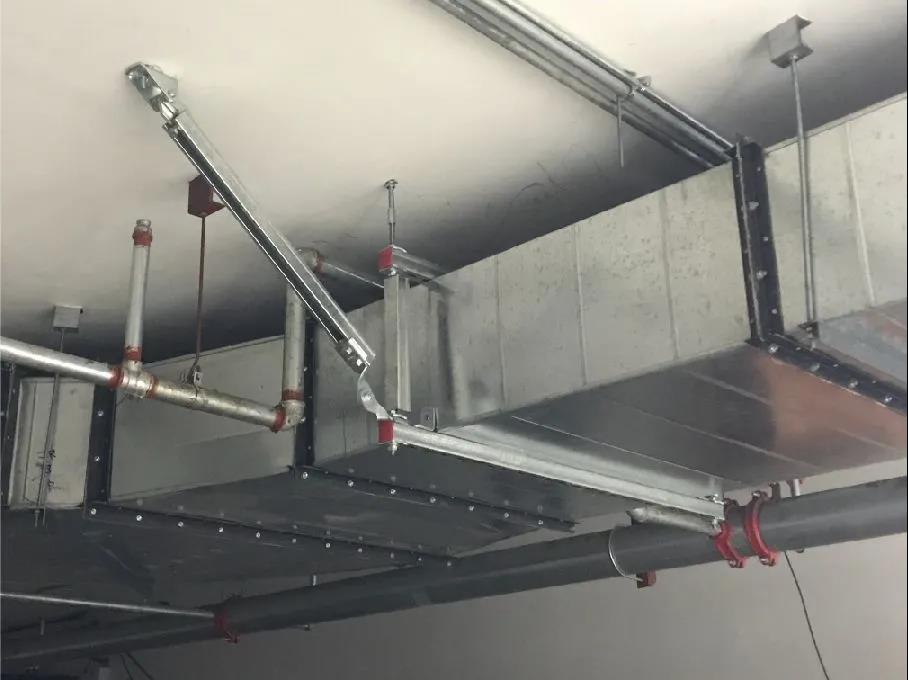
对于单根管道(包括风管、水管、电缆等)的吊架,要求不大于12m做一对水平拉杆,不大于24m做一对垂直拉杆。对于此种吊挂形式,无论管道长短,要至少有两对水平拉杆和一对垂直拉杆。
对于用槽钢或者角钢做成的用来放置多根管道的支架,当其中管道直径都小于100mm时,每隔12m做一对水平和垂直的拉杆,当其中的管道直径在100mm~200mm时,每隔6m做一对水平和垂直的拉杆。而且对于此种支架要求在端部必须加水平和垂直的拉杆。
下表给出对应的管道重量(包括支架重量),按照公式计算出来的拉杆的拉力,和推荐的吊杆形式。其中连接拉杆和支架及结构构件的五金件选用时要求要能满足表中所列出的拉力值,必须有相应的资料和报告证明其设计承载力大于相应的拉力值方可使用。下表中的拉杆安装的角度要求在35度到55度之间。
单根管道的拉杆的抗震设计值
管道重量Wp (kg/m) | 杆1拉力(kN) | 杆2拉力(kN) | 强度为890Mpa的不锈钢吊杆 | Q235圆钢吊杆 | 8.8级A级普通螺栓 |
10~20 | 4 | 8 | Ф6 | Ф6,Ф8 | M10 |
20~50 | 10 | 19 | Ф6 | Ф8,Ф12 | M10,M12 |
50~100 | 19 | 38 | Ф6,Ф8 | Ф12,Ф16 | M12,M16 |
100~200 | 37 | 74 | Ф8,Ф12 | Ф16,Ф22 | M16,M20(2M16) |
支架形式的拉杆抗震设计值(用于12m一对拉杆)
管道重量Wp (kg/m) | 杆1拉力(kN) | 杆2拉力(kN) | 强度为890Mpa的不锈钢吊杆 | Q235圆钢吊杆 | 8.8级A级普通螺栓 |
10~20 | 4 | 4 | Ф6 | Ф6 | M10 |
20~50 | 10 | 10 | Ф6 | Ф8 | M10 |
50~100 | 19 | 19 | Ф6 | Ф12 | M12 |
100~200 | 37 | 37 | Ф8 | Ф16 |
支架形式的拉杆抗震设计值(用于6m一对拉杆)
管道重量Wp (kg/m) | 杆1拉力(kN) | 杆2拉力(kN) | 强度为890Mpa的不锈钢吊杆 | Q235圆钢吊杆 | 8.8级A级普通螺栓 |
10~20 | 2 | 2 | Ф6 | Ф6 | M10 |
20~50 | 5 | 5 | Ф6 | Ф6 | M10 |
50~100 | 10 | 10 | Ф6 | Ф8 | M10 |
100~200 | 19 | 19 | Ф6 | Ф12 | M12 |
符合下列要求的管道可不做抗震措施。
1.重量小于180kg的悬挂设备。
2.内径小于25mm的煤气管道和内径小于60mm的电气配管。
3.矩形面积小于0.38m2和圆形直径小于0.70m的风管。
4.吊杆计算长度不超过300mm的吊杆悬挂管道。
5.直径小于55mm的水管。
6.对于易燃易爆和有毒性的气体或者液体管道,需要按照相关的规范确定。
此版本提供了抗震支撑安装时,8.8级A级普通螺栓的选型型式。如果采用膨胀螺栓,必需保证使用的膨胀螺栓(一个或者一组)的抗拉力大于表中所列的拉力。其中需要注意的是在五金件和连接件的采购中,要根据现场管道的型式和重量,采用对应螺栓孔大小的五金件和连接件,避免因为采购的五金件和连接件上预留的螺栓孔直径不够,导致螺栓无法安装。
GUIDE OF SEISMIC BRACE FOR PIPE RACK
(REV.2 2006.11.14)
The guide is used to restraint seismic for pipe and duct racks in AMAT project. The guide follow the UBC1997 regarding non-structural seismic design section.
For single pipe including pipe /duct /conduit, the brace space must be not more than 12m in latitudinal way, and not more than 24m in longitudinal way.
For pipe rack that composed with angle or channel, if the entire pipes diameter is less than 100mm, the brace space must be not more than 12m in latitudinal and longitudinal way. If the entire pipes diameter is between 100mm to 200mm, the brace space must be not more than 6m in latitudinal and longitudinal way. And the latitudinal and longitudinal brace need be installed at the each end of the pipe run.
You can find the tension of brace and member size of the brace that I recommendate per pipes weight in the table below. Before the installation of the brace, the subcontractor need get the material report to testify the load-carrying capacity of member and connection are more than the tension of brace that show in the table below. The angel of the brace should be between 350 to 550.
Seismic force of brace for single pipe:
Pipe weight Wp (kg/m) | Tension of brace 1 (kN) | Tension of brace 2 (kN) | Stainless steel rod (fy= 890Mpa) | Q235 rod (fy= 210Mpa) | Grade 8.8 bolt (ft= 400Mpa) |
10~20 | 4 | 8 | Ф6 | Ф6,Ф8 | M10 |
20~50 | 10 | 19 | Ф6 | Ф8,Ф12 | M10,M12 |
50~100 | 19 | 38 | Ф6,Ф8 | Ф12,Ф16 | M12,M16 |
100~200 | 37 | 74 | Ф8,Ф12 | Ф16,Ф22 | M16,M20(2M16) |
Seismic force of brace for pipe rack (applicable to brace space < 12m):
Pipe weight Wp (kg/m) | Tension of brace 1 (kN) | Tension of brace 2 (kN) | Stainless steel rod (fy= 890Mpa) | Q235 rod (fy= 210Mpa) | Grade 8.8 bolt (ft= 400Mpa) |
10~20 | 4 | 4 | Ф6 | Ф6 | M10 |
20~50 | 10 | 10 | Ф6 | Ф8 | M10 |
50~100 | 19 | 19 | Ф6 | Ф12 | M12 |
100~200 | 37 | 37 | Ф8 | Ф16 | M16 |
Pipe weight Wp (kg/m) | Tension of brace 1 (kN) | Tension of brace 2 (kN) | Stainless steel rod (fy= 890Mpa) | Q235 rod (fy= 210Mpa) | Grade 8.8 bolt (ft= 400Mpa) |
10~20 |
The pipes and ducts without anti-seismic requirement are below:
A. Utility that weight is less than 180kg.
B. φ< 25mm coal gas pipe and φ< 60 mm electrical conduit
C. Area < 0.38 m2 rectangular and
Copyright © 2020 All Rights Reserved 版权所有:优槽新材料科技(上海)有限公司 沪ICP备11016284号 网站制作:苏州万户网络