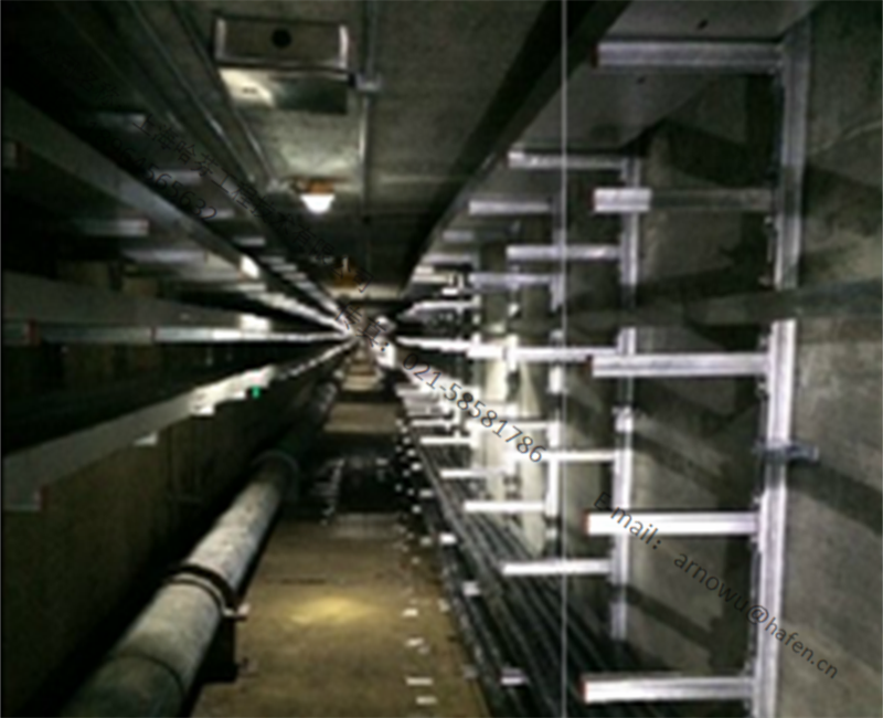
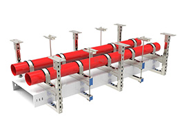
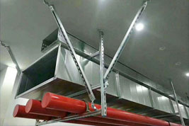
Design of pipe gallery height
(1) Crossing the sky above the road: minor road 4.5; main road 6m or more; railway 7m or more; the clear height of the inspection passage is not less than 3.1m.
(2) The height of the lower equipment: at least 2.5m around the pump; 5.5m on the heat exchanger; when the pipe on the pipe gallery is connected to the equipment, the minimum clear height is 3.5m.
(3) Consider the beam structure and section type: For double-layer pipe corridors, the distance between the upper and lower floors is 1-1.5m.
The height of the pipe gallery between installations needs to be considered across regions. The whole plant adopts a standard to coordinate with other installations.
Design of pipe gallery height
The width of the pipe gallery is mainly determined by the number of pipes and pipe diameter (the densest place), and a certain margin (20%) is added. consider:
(1) Equipment and passages under the pipe gallery.
(2) Pipe spacing: The calculation method is different in different documents.
Generally, the width of the pipe gallery is 6-10m, and part or all of the double-layer pipe gallery is used for more than 9m.
Pipe frame structure
There are single-column pipe racks and double-column pipe racks. The width of the single-column pipe rack is 0.5, 1, 1.5, 2, and 3 meters; the double-column pipe rack width is 3, 4, 6, and 8 meters. A single steel pipe or reinforced concrete column plus steel beam structure is adopted, and a large-scale reinforced concrete frame structure is adopted.
Column distance of pipe gallery and span of pipe rack
(1) The column distance of the pipe gallery and the span of the pipe rack are determined by the bending stress and deflection of the pipe laid on it;
(2) The column distance of the pipe gallery and the span of the pipe rack are determined by the allowable span of the smallest pipe laid on it or the allowable span of most pipes.
(3) The span of the pipe rack is 6-8m, and the pipe below DN40 is 3-4m.
Layout of the pipes on the pipe gallery
Consider the factors of pipe diameter: large-diameter pipes are as close as possible to the columns of the pipe gallery, and single-column pipe rack pipes are evenly arranged on both sides of the pipe rack columns.
1) Consider the factor of equipment location: in accordance with the connected equipment, the utility pipeline is arranged in the center.
2) Consider the nature of the material being transported: low-temperature pipes, unheated pipes and hot pipes are arranged separately, and corrosive media are laid in the lower layer.
3) Consider the influence of thermal stress: high temperature pipelines and normal temperature pipelines consider thermal expansion according to the temperature of the purging medium, and the high temperature and large diameter are on the outside.
4) Consider the safety of instrument piping and power cables: underground cables are laid in the process area. Where corrosive liquid penetrates, use overhead trough boards to lay, and instrument piping is considered together with cables. Cables are not allowed to be arranged near hot pipes or under corrosive media. They are generally laid under the corridors or outside the pillars of the corridor.
Factors to be considered in the determination of the width, span and height of the main gallery in the installation
(1) Width of pipe gallery
1) The width of the pipe gallery is mainly determined by the number of pipes and the size of the pipe diameter. And consider a certain reserved width. Generally, the main pipe rack should have a margin of 10%-20%, and consider its load. At the same time, the influence of the equipment and channels under the pipe gallery and the air-cooling equipment on the pipe gallery should be considered. If it is required to lay instrument cable trays and power cable trays, the required width should also be considered. The pipes on the pipe gallery can be arranged in single or double layers, or three layers if necessary. The width of the pipe gallery should generally not be greater than 10m;
2) When the air cooler is arranged on the pipe gallery, the span of the pillars should be the same as the spacing of the air cooler, so that the pipe gallery column is aligned with the center line of the air cooler pillar;
3) When arranging the pump under the pipe gallery, the layout of the pump and the width of the required operation and maintenance channels should be considered. If the pump driver cable is laid underground, the required width of the cable trench should also be considered. In addition, the required width of the main pipe of the pump cooling water pipe and drain pipe must be considered;
4) Because the pipeline layout density of the entire pipe gallery is not the same, the number of pipes in the first and last pipe gallery is usually less. Therefore, when necessary, the width of the first and last section of the pipe gallery can be reduced or the double-layer pipe gallery can be transformed into a single-layer pipe gallery.
(2) The span of the pipe gallery:
The column distance of the pipe corridor and the span of the provincial corridor are determined by the allowable bending deflection of the pipelines laid on it due to the vertical load, usually 6-9m. For example, in small and medium-sized devices, when there are many small-diameter pipes, an auxiliary beam can be set between the two pillars to reduce the span of the pipe. In addition, the spacing of the pipe gallery columns should be consistent with the spacing of the equipment frame pillars so that the pipeline can pass through. If it is a concrete pipe frame, a φ20 round steel or steel plate should be buried on the top of the beam to reduce the friction between the pipe and the beam.
(3) The height of the pipe gallery can be determined according to the following conditions:
1) Space that crosses the road. When the pipe gallery crosses over the road, its clearance height is:
① The maintenance path in the device should not be less than 4.5m;
②The factory road should not be less than 5.0m;
③The railway should not be less than 5.5m;
④ The maintenance passage under the pipe gallery shall not be less than 3m.
When the pipe gallery has a truss, it shall be calculated according to the bottom height of the truss.
2) The minimum height of the pipe under the pipe gallery. In order to effectively use the pipe gallery space, pumps are often arranged under the pipes. Taking into account the operation and maintenance of the pump, at least 3.5m is required; when the pipeline on the pipe gallery is connected to the zoned equipment, it should generally be 600-1000mm lower than the bottom pipe of the pipe gallery. Therefore, the minimum size of the bottom of the pipe gallery is 3.5m. When the shell-and-tube cold exchange equipment is arranged under the pipe gallery, the clearance under the pipe gallery needs to be increased due to the increase in the height of the equipment.
3) The height difference of pipe corridors intersecting vertically. If the provincial corridor changes direction or the two pipe corridors intersect at right angles, the height difference depends on the minimum size of the pipe interconnection, generally 500-750mm is appropriate. 1000mm height difference can also be used for large devices.
4) The structural size of the pipe gallery. When determining the height of the provincial corridor, the structural section and type of the pipe corridor beams and longitudinal beams must be considered, and the height of the bottom of the beam and the bottom of the frame must meet the above requirements for determining the height of the pipe corridor. For a double-layer pipe gallery, the distance between the upper and lower layers is generally 1.2-2.0m, which is mainly determined by the diameter of the largest pipe on the pipe gallery.
5) As for the height of the pipe gallery between the devices, it depends on the specific conditions of the area where the pipe rack passes. If the tank area is formed along the edge of the factory, it will not affect the traffic and expansion of the factory area. Considering the economy and convenience of maintenance, it can be laid by pipe piers, and the requirements can be met by 300-500mm above the ground.


